Why Outsourcing 3D CAD Modeling Breaks at the Assembly Line
The digital render on the conference room screen was an absolute work of art. It was a next-generation medical device enclosure, boasting sleek compound curves, seamless mating lines, and perfectly flush buttons. The offshore CAD engineering firm had delivered the files right on schedule, the internal design review board had signed off on the visuals, and the executive team authorized a $65,000 budget for the initial factory tooling and prototype run.
Six weeks later, a crate of physical parts arrived at the company’s assembly facility.
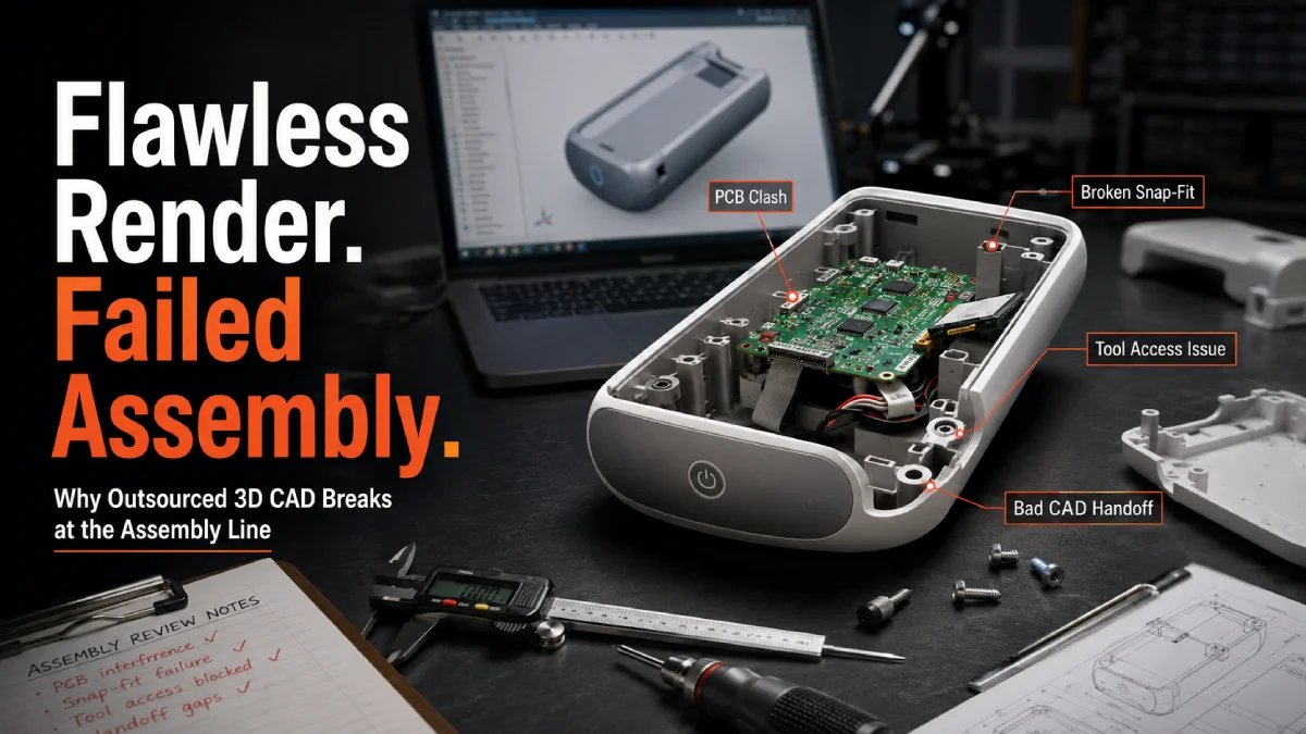
The dream vanished the moment a technician tried to put them together. The internal printed circuit board (PCB) physically clashed with a structural mounting boss by less than half a millimeter. When they tried to force the enclosure shut, the stress snapped a delicate plastic snap-fit clip. Worse, a factory worker pointed out that a crucial internal fastening screw was positioned in a pocket so narrow that no physical screwdriver in the facility could actually reach it.
On screen, the 3D product assembly was flawless. In the physical world, it was expensive plastic scrap.
This is the hidden crisis of modern hardware development. In an era where companies routinely outsource 3D CAD modeling to optimize operational budgets, many treat 3D data as a simple commodity like copywriting or data entry. But a 3D CAD assembly is not a static digital illustration. It is the complex, relational digital DNA of a physical product. If that DNA is mutated by poor modeling practices, data fragmentation, or a lack of manufacturing literacy, the entire downstream supply chain gets sick.
To successfully scale external engineering, hardware brands must look past the sleek digital renders and confront the invisible friction of outsourced CAD assemblies.
1. The “Baked Cake” Trap: The Hidden Friction of Interoperability
When outsourcing CAD design, companies frequently run into a software mismatch. The internal engineering team might run SolidWorks, while the external agency works in Autodesk Inventor or Creo. The common compromise is to ask the vendor to deliver the final files in a neutral, universal format like a STEP or IGES file.
On the surface, this feels like an elegant solution. The native file opens cleanly in your software, the geometry looks perfect, and you can rotate the 3D model effortlessly.
However, this introduces what engineers call a “dumb solid.”
| Stage | Native CAD File | Exported STEP File | Your In-House Team |
|---|---|---|---|
| Data Content |
|
|
|
| Usability |
Full editability and design intent retained. |
Interoperability format with static geometry. |
High effort to modify and prone to errors. |
A native CAD assembly file relies on an intricate web of active links. It remembers the step-by-step history of how a part was built (the feature tree) and precisely how parts relate to one another (mates and constraints). When you export an assembly to a neutral STEP file, the software strips away all this intelligence.
Exporting a complex CAD assembly to a STEP file is like baking a cake. You can see it, you can measure its dimensions, and you can slice it. But if you realize the recipe needs less sugar, you can no longer pull the grains of sugar out of the baked sponge. If your in-house team needs to modify a wall thickness or adjust an internal rib on an outsourced STEP file, they can’t simply edit a numerical value. They are forced to manually cut, extrude, and hack a static shape—a process that introduces massive technical debt and frequently requires a total rebuild.
2. Bad Parametric Hygiene and the Falling Domino Effect
Even when outsourced vendors work in the exact same native software version as your internal team, structural failures can lurk beneath the surface of the file. This is the domain of parametric hygiene.
Good CAD design uses logical, intent-driven relationships. For example, if an engineer models a bracket that holds a cylindrical motor, they will constrain the bracket’s curve to the motor’s outer diameter. If the motor supplier changes the motor diameter from 50mm to 55mm next month, the engineer simply changes that single input value, and the bracket automatically updates its geometry to match.
Inexperienced or rushed external modelers often rely on “lazy” modeling. Instead of linking parts dynamically, they fix components to static, absolute coordinates in space or use arbitrary dimensions to get the job done quickly.
The Falling Domino Effect
Imagine an in-house engineer opening a poorly constructed assembly to make a routine modification, such as widening an enclosure by 5mm to accommodate a larger battery. Because the external designer didn’t build smart parametric relationships, that 5mm change causes a catastrophic failure cascade across the feature tree.
Mating relationships break. Screw holes remain fixed in space while the walls move away from them. Mating lips twist inside out. The CAD interface lights up with red error flags. What should have been a two-minute design adjustment turns into a three-day forensic investigation to figure out how the external modeler originally constructed the file.
3. The Dangerous Illusion of “Screen Realism”
The most deceptive aspect of 3D modeling is that the digital workspace is an ideal environment with zero friction, zero gravity, and absolutely perfect manufacturing capabilities. The software allows a 10.000mm metal pin to slide perfectly into a 10.000mm hole.
But out on the factory floor, perfection does not exist.
When outsourced modelers lack practical manufacturing experience or direct exposure to your specific production vendors, they design for the screen rather than the factory floor. They often neglect Tolerance Stack-Up Analysis and GD&T (Geometric Dimensioning and Tolerancing).
If five separate injection-molded and stamped-metal parts are stacked next to each other, and each part varies by just 0.05mm due to completely normal factory variances, the total assembly variance can stack up to a quarter of a millimeter. In precision electronics or high-stress mechanical systems, that tiny discrepancy means the final product cannot be assembled without physical force, resulting in structural stress, rattling, or immediate mechanical failure.
Furthermore, a remote modeler who hasn’t stepped onto an assembly line may completely miss crucial Design for Manufacturing (DFM) guidelines:
- Modeling deep vertical plastic walls without a draft angle (a slight taper), making it physically impossible for the factory tool to eject the cooled plastic part without tearing it.
- Placing hardware fasteners so close to structural ribs that standard assembly tools cannot fit into the space to tighten them.
- Designing snap-fit mechanisms that require the plastic to bend beyond its material yield strength during assembly, causing immediate fractures on the production line.
4. Version Chaos and Broken Data Links
A 3D product assembly is almost never a single monolithic file. Instead, it operates like a web ecosystem: a master assembly file acts as a directory that references dozens or hundreds of individual part files.
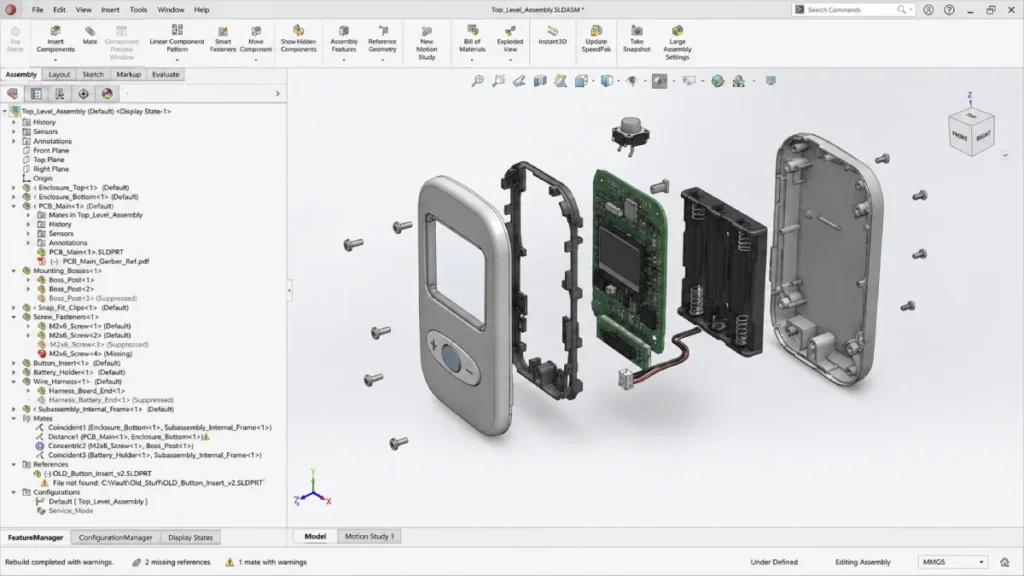
If you outsource this work and manage the relationship through traditional communication channels like email, Slack, or basic file-sharing links, version control rapidly disintegrates into chaos.
Consider this common scenario: an outsourced engineer is tasked with modifying a internal support bracket to clear a wire harness. They open the file locally on their machine, make the change, save it as Bracket_rev2.prt, and update their local assembly. They then email you the updated bracket file.
However, when your team drops that new bracket file into your local server, the master assembly file—which is still looking for the original file path or naming convention—throws a critical “Broken File Link” error. Alternatively, if the vendor fails to send over a tiny, modified internal washer file buried deep within a sub-assembly, the entire top-level model becomes corrupted.
Without a shared, synchronized data environment, managing design updates across different time zones quickly turns into a game of digital Russian roulette. You run a very real risk of accidentally sending an unrevised, outdated version of a component file to your production tooling vendor.
5. The Governance Framework: Building a Bulletproof CAD Bridge
Outsourcing 3D CAD modeling can be incredibly efficient, giving you access to specialized global talent and allowing your core team to focus on high-level architecture. However, capturing that value requires treating the external vendor as a tightly integrated node in your engineering ecosystem, rather than an isolated supplier.
To eliminate the invisible friction of outsourced assemblies, engineering leaders should deploy a strict three-part governance framework.
A. Establish an Immutable CAD Style Guide
Before an external designer draws a single line, hand them an explicit technical blueprint for how their files must be constructed. Do not leave the file structure to their discretion.
- Dictate the exact software version and service pack to be used throughout the project lifecycle.
- Standardize the naming conventions for parts, sub-assemblies, and configuration files.
- Require a specific modeling methodology such as a top-down skeleton framework, where all primary parts are driven by a central, master control sketch, ensuring predictable updates.
B. Enforce a Single Source of Truth
Eliminate file transfers via email or cloud storage links entirely. Force your outsourced partners to work directly inside your version-controlled PDM (Product Data Management) or PLM (Product Lifecycle Management) environment—such as SolidWorks PDM, Autodesk Vault, or cloud-native platforms like Onshape.
- Utilize strict check-in/check-out permissions to ensure that only one engineer can modify a specific component at any given time.
- Maintain a real-time, unalterable digital audit trail of exactly who changed which dimension, when they changed it, and why.
C. Implement an Automated Quality Gate
Establish clear, non-negotiable technical criteria that every delivered assembly file must pass before milestone payments are unlocked or files are pushed downstream.
Automated Clash & Interference Check
Run an algorithmic clearance analysis across the entire assembly to ensure zero physical intersections exist between components at nominal dimensions.
Kinematic & Motion Simulation
Actuate moving parts through their entire dynamic range of travel to verify clear operational envelopes and confirm that components do not collide during use.
Manufacturing Feasibility (DFM) Audit
Deploy automated software checks to audit the model for critical production metrics, ensuring proper draft angles for molded parts and adequate tool clearance for fasteners.
Parametric Stability Stress-Test
Intentionally alter core dimensions by +/- 10% to ensure the feature tree recalculates cleanly without throwing errors or breaking geometric constraints.
Mastering the Digital Handoff
In the modern manufacturing landscape, the competitive boundary between agility and failure is defined by data integrity. A stunning 3D render is highly effective for investor pitches and marketing materials, but the factory floor only cares about clean math, physical tolerance logic, and stable file architecture.
Outsourcing product assembly 3D CAD modeling successfully isn’t a race to find the lowest hourly labor rate. It is an exercise in technical governance. By setting rigorous parametric standards, mandating a shared data environment, and auditing files for real-world manufacturing limits, companies can confidently leverage global design talent, ensuring that the flawless product on the screen is exactly what rolls off the assembly line.
Ready to bring your concepts to life?
At ZetaCADD, our team of experienced engineers is here to discuss your 3D CAD modeling project and explore how we can support your design, development, and manufacturing needs. Whether you have a fully-defined project or just a conceptual idea, we can provide the expertise and resources to turn your vision into reality.