

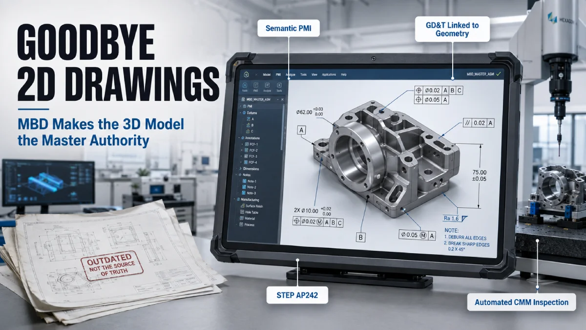
Model-Based Definition (MBD) Guide: Eliminating 2D Drawings in CAD Pipelines
The traditional mechanical design pipeline contains an expensive, hidden redundancy. An engineer spends weeks building a highly constrained, parametrically intelligent 3D CAD model. Then, they spend an additional 40% of their total project time flattening that model into static, 2D projection drawings (PDFs or DWGs) so the machine shop can interpret dimensions, tolerances, and datums.
This process introduces a massive point of failure: the dual-source truth.
The moment a geometric value is changed in a 3D file but missed on the 2D sheet, the digital DNA of the product breaks. For enterprises scaling complex assemblies, the path forward isn’t better drawing management; it is the total elimination of the 2D drawing through Model-Based Definition (MBD).
True MBD treats the 3D model as the single, legally binding source of authority, embedding Product and Manufacturing Information (PMI) directly into the digital geometry. Here is the technical roadmap for executing this transition successfully.
1. The Anatomy of Semantically Enriched PMI
Many companies mistake “putting 3D annotations on a screen” for MBD. If an engineer simply slaps a text note onto a 3D view, they have merely created a 3D sticky note. This is graphical PMI, and it still requires human eyes to read it and type it into a CNC machine.
True enterprise MBD relies on semantic PMI.
| Element | Component Definition | Technical Implementation | Downstream Automation |
|---|---|---|---|
| 3D Geometry Feature | The physical CAD topology, such as a cylindrical bore, planar surface, or complex slot. | Underlying surface ID mapped directly inside the CAD database architecture. | Evaluated directly by machine tools without manual geometry creation. |
| Semantic PMI Data Block | Digital link containing GD&T parameters, tolerance limits, and datum references. | Geometric tolerances, such as ±0.02 mm linked to Datum A, embedded as machine-readable metadata. | Computer-Aided Manufacturing (CAM) software auto-reads paths, calculating feeds and speeds directly. |
In a semantically enriched model, a Geometric Dimensioning and Tolerancing (GD&T) feature control frame is digitally linked to the underlying CAD faces and edges. If a true position tolerance is applied to a hole, the CAD database explicitly knows that the tolerance applies to the cylindrical surface ID rather than just a coordinate point in space. This machine-readable data allows CAM software to automatically ingest the model, recognize the tolerance constraint, and program the toolpaths or feeds without human intervention.
2. Navigating the Standards: ASME Y14.41 and ISO 16792
You cannot execute MBD across a global supply chain without strict adherence to international standards. Decision-makers must baseline their CAD style guides against two critical frameworks:
- ASME Y14.41 (Digital Product Definition Data Practices): The gold standard for American manufacturing. It dictates exactly how 3D data sets must be structured, how “saved views” (orientations) must display annotations to prevent visual clutter, and how geometric scale and coordinate systems must be declared.
- ISO 16792: The international equivalent. It provides the technical governance for specifying requirements (such as surface texture, weld symbols, and material specifications) directly within the 3D digital space.
Without enforcing these standards in your vendor contracts, external suppliers will reject your 3D models, claiming they are legally ambiguous.
3. The Downstream Multiplier: Connecting CAD to CMM (Inspection)
The true ROI of MBD is realized after the design phase. The most technical bottleneck in manufacturing is often quality control, specifically programming coordinate measuring machines (CMM) to inspect physical parts.
Traditionally, a quality engineer looks at a paper print, manually writes a CMM inspection routine, and physically probes the parts. The transition to MBD transforms this entirely automated pipeline:
| Pipeline Stage | Data Input | Preservation Format | Downstream Quality Execution |
|---|---|---|---|
| Semantic MBD Model | Complete 3D geometric assembly alongside comprehensive embedded PMI data. | Native digital engineering environment. | Acts as the foundational source of master authority. |
| STEP AP242 Export | Precise surface geometry translated alongside unbroken semantic annotations. | Neutral schema preserving exact links between GD&T values and face IDs. | Serves as the universal language for multi-vendor manufacturing platforms. |
| Automated CMM Programming | Inspection software ingests the neutral file, mapping features directly to measuring probes. | Fully computerized path layout matching original design intent. | Eliminates manual CMM programming, generating inspection routines automatically. |
With a semantic MBD workflow, the inspection software reads the digital PMI directly. The software automatically recognizes that Datum A is the primary locating face and that a specific bore has a cylindrical tolerance of 0.05 mm. The system generates the CMM probe paths automatically. This compresses inspection programming time from days to minutes and eliminates human transcription errors entirely.
4. Solving the Interoperability Problem: STEP AP242
The primary operational hurdle to MBD adoption is vendor tool compatibility. If your enterprise uses SolidWorks, your machine shop uses Creo, and your injection molder runs NX, how do you transmit semantic PMI without losing data integrity? The answer lies in moving beyond legacy file types to unified engineering data schemas:
| File Format Schema | Geometric Content | Semantic & Graphical PMI Support | Data Integrity for MBD |
|---|---|---|---|
|
Legacy STEP (AP203 / AP214) |
Exploded boundary representation (B-rep) surfaces and solid shapes. | None. Requires secondary 2D prints or manual annotation text entry. |
Fail Results in static “dumb solids” without design intent or manufacturing intelligence. |
|
Modern STEP (AP242) |
Complete 3D geometric definitions, including complex assembly hierarchies. | Full semantic and graphical annotation integration tied directly to geometric features. |
Pass Maintained data structure allows automated programming throughout the entire supply chain. |
Unlike legacy formats that only export unlinked surface geometry, AP242 was built specifically for MBD. It handles both graphical annotations (for human viewing) and semantic annotations (for machine consumption) while preserving the exact links between the GD&T data and the 3D geometry.
The Technical Transition Checklist for Engineering Leaders
Before shifting your pipeline to an MBD framework, ensure your operations team can check off these four infrastructure requirements:
- CAD Template Standardization: Establish strict “Combination State” or “3D View” naming conventions in your master templates so downstream vendors can quickly isolate dimensions by category (such as Machining, Inspection, or Thermal constraints).
- Schema Validation: Implement automated validation tools (such as CADIQ or similar PLM gateways) to verify that data has not degraded or shifted when converting native files to neutral STEP AP242 formats.
- Hardware on the Shop Floor: Reallocate budget from paper plotters to ruggedized, high-resolution view stations on the manufacturing floor, allowing operators to dynamically rotate, section, and query the live 3D assembly.
- Legal Sourcing Updates: Revise Master Services Agreements (MSAs) with suppliers to explicitly state that the 3D CAD digital file is the Master Authority, and any printed reference materials are for convenience only.
Ready to systematically eliminate 2D overhead from your design pipeline?
At ZetaCADD, our advanced engineering services team specializes in architecting enterprise MBD transitions, structuring semantic PMI schemas, and optimizing downstream CAM/CMM integrations. We ensure your digital assets are built to international standards, providing the absolute data integrity required to accelerate your time-to-market.
Contact us today for a comprehensive technical consultation.